4 Terminal Capacitor Wiring Diagram

Mitsubishi Alternator Wiring Diagram Alternator Car Alternator
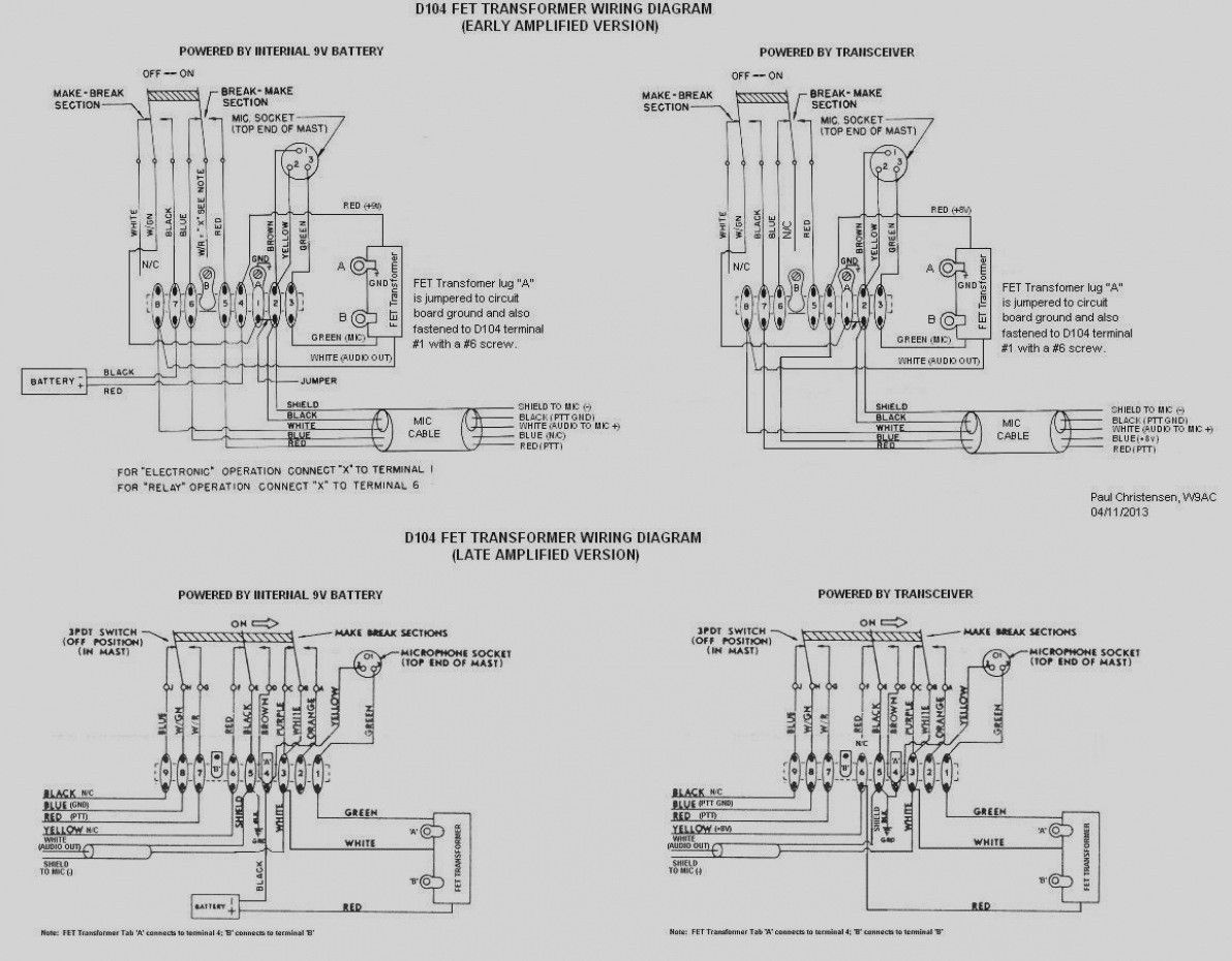
D104 Microphone Wiring Diagram D104 Radio Shop

Relay Switch Wiring Diagram Beautiful Led Light Bar Wiring Mit
Ray great.

4 terminal capacitor wiring diagram. Using a single run capacitor with a four wire setup. If an hvac fan motor capacitor just has 2 terminalson its top they will be f fan and c common. Hvac shop talk podcast represents the blue collar boys and girls in the skilled trades especially hvac. Do i remove it or is it safe to leave it.
Thread starter paul hemans. A motor that also can have its run direction swapped between clockwise and counterclockwise adding 2 to 4 wires. Joined jul 8 2015 4. Factory power wiring factory control wiring field control wiring field power wiring component connection field splice junction cont contactor cap capacitor dual run 317738 401 rev.
The wires connected to the motors common terminal marked c or com on the motors wiring chart also connect to this. Hvac capacitor wiring number of terminals wiring color codes terminal identification codes. To be wired in accordance with national electric nec. How to wire up a start capacitor by.
I would like to suggest that you look at the wiring diagram that came with your ac unit to try and figure out the wiring. Will it cause ether fan to overspend andor any damage. 3 terminals capacitor air conditioner wiring diagram hindi air conditioner repair service in mira road review link httpsgoogleqotgd call 8879979540 wwwbtenaircoolin. In this video zack psioda explains how many dual run capacitors are wired in heat pump and.
July 27 2018 at 1132 am. The wiring diagram said to hook it up to the common lead on the capacitor. I just replaced the fan motor and capacitor the original motor had 3 wires the new 4. Jul 4 2016 1 attached image is a green cap 500f 27v capacitor mh47765 i dont understand the connections.
Often a stamp on the side of the relay shows the wiring diagram. Step 3 push the wire terminal on the start capacitor relays common wire usually the black wire to the common terminal on the load side of the units contactor. Why does this capacitor have 4 terminals. I have never seen where there are two wires connected to the fan terminal of the capacitor.
Symbols are electrical representation only. One is obviously and another opposite is marked as are the other 2 just for support on a circuit board.

Car Audio System Wiring Basics Ebay 484x365 Jpeg With Images

Subwoofer Wiring Diagrams With Diagram Dual 1 Ohm Gooddy Org For

Wiring Diagram Bathroom Lovely Wiring Diagram Bathroom Bathroom

Bosch 4 Pin Relay Wiring Diagram For Doorbell Symbols Car

27 Best Heat Pump Air Conditioner Images In 2020 Refrigeration

Wiring Diagram Cars Trucks 1948 Ford Truck Ford Diagram

1811 Best Wiring Diagram Sample Images Diagram Electrical

Wiring Diagram For Ac Unit Elegant Goodman Condenser Wiring With

16 Wiring Diagram For Electric Fireplace Heater With Images
